Imhoff tank
This article needs additional citations for verification. (July 2021) |

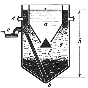
The Imhoff tank, named for German engineer Karl Imhoff (1876–1965), is a chamber suitable for the reception and processing of sewage. It may be used for the clarification of sewage by simple settling and sedimentation, along with anaerobic digestion of the settled sludge [1]. It consists of an upper chamber in which sedimentation takes place, from which settled solids slide down on the inclined bottom slopes towards a lower chamber in which the sludge accumulates. The two chambers are otherwise unconnected, with the more liquid sewage flowing only through the upper sedimentation chamber and only a slow flow of sludge in the lower digestion chamber. The lower chamber requires separate biogas vents and pipes for the removal of digested sludge, typically after 6–9 months of digestion.[2] The Imhoff tank is in effect a two-story septic tank [3] and retains the septic tank's simplicity while eliminating many of its drawbacks, which largely result from the mixing of fresh sewage and septic sludge in the same chamber.
Typically, well-designed and operated Imhoff tanks are expected to remove suspended solids with an efficiency between 50-70% [4]. Effluent coming out from Imhoff tanks can be either discharged in the environment, sent to a centralized wastewater treatment facility, or sent to constructed wetlands for disinfection and nutrient removal.
As a result of anaerobic digestion of settled sludge, methane, carbon dioxide, hydrogen and hydrogen sulphide are typically formed [5]. While in the past this gas mix used to be exploited for energy production given the relatively high methane content [6], nowadays gas from Imhoff tanks is typically vented out in the environment. This wastes the energy potential recovery of the technology and increases its carbon footprint, given the high content of methane which has a global warming potential about 25 times larger than the one of carbon dioxide [7].

Imhoff tanks are being superseded in sewage treatment by plain sedimentation tanks using mechanical methods for continuously collecting the sludge, which is moved to separate digestion tanks. This arrangement permits both improved sedimentation results and better temperature control in the digestion process, leading to a more rapid and complete digestion of the sludge.
A test for settleable solids in water, wastewater and stormwater uses an Imhoff cone, with or without stopcock. The volume of solids is measured after a specified time period at the bottom of a one-liter cone using graduated markings.[8]
See also[edit]
References[edit]
- ^ Hatfield, W.D.; Morkert, K. The Removal of Suspended Solids and Production of Gas by the Imhoff Tanks of Decatur, Illinois. Sewage Work. J. 1932, 4, 790–794. https://www.jstor.org/stable/25028203
- ^ "Imhoff Tank | SSWM". sswm.info. Retrieved 2023-02-07.
- ^ Beaumont, H. M. (1929). "The Operation of Imhoff Tanks". Sewage Works Journal. 1 (2): 211–217. ISSN 0096-9362.
- ^ Mahlie, W. S. (1939). "A Comparison of the Performance of Imhoff Tanks against Primary Settling Tanks". Sewage Works Journal. 11 (1): 68–71. ISSN 0096-9362.
- ^ Nugent, B.J. Operation of New Castle Sewage Plant. Sewage Work J. 1931, 3, 404–410. https://www.jstor.org/stable/25028056
- ^ Donaldson, W. Gas Collection from Imhoff Tanks. Sewage Work. J. 1929, 1, 608–614. https://www.jstor.org/stable/25037040
- ^ Boiocchi, Riccardo, Matia Mainardis, Elena Cristina Rada, Marco Ragazzi, and Silvana Carla Salvati. 2023. "Carbon Footprint and Energy Recovery Potential of Primary Wastewater Treatment in Decentralized Areas: A Critical Review on Septic and Imhoff Tanks" Energies 16, no. 24: 7938. https://doi.org/10.3390/en16247938
- ^ Imhoff Cone, Retrieved 2012-05-29.
